The roots of the forest
The mesh topology of p4est is a general forest of octrees.
Each octree is a logical hypercube.
To represent a general and possibly non-cubic domain \(\Omega\),
we begin by covering it with a conforming mesh of (potentially mapped)
squares (2D) or cubes (3D).
This coarsest possible mesh or
- Use as many cubes as needed to capture the domain's topology (connected components, holes, tunnels, etc.).
- Invest some more cubes to achieve an ideally uniform individual aspect ratio of each cube.
- Invest some more cubes if the distortion in any single mapped octree appears too large.
- Reduce the number of octrees if the coarse mesh must be limited for numerical reasons.
We have successfully connected millions of octrees. Below 100k, there is no need to even think about reducing their number if the procedure would not be obvious. The connectivity is the first data structure that is built in a p4est program. This tutorial covers its definition and ways to construct it.
- Dependencies
- Build
- Required skills
-
Knowing about the C language's
structand array data types. Optional: using valgrind; using a debugger. - Skills acquired
- Creating and destroying p4est connectivity structures. Saving them to a file and loading them later.
- Next steps
- Construct several connectivities by builtin constructor functions. Construct a connectivity by hard-coding its members yourself. Use each connectivity to construct a coarse p4est and visualize it via the VTK output.
The p4est_connectivity data structure
The convention for the connectivity's members is documented separately for the
2D connectivity and the
3D connectivity.
Note that we prefix 2D functions and objects with p4est and their
3D cousins with p8est.

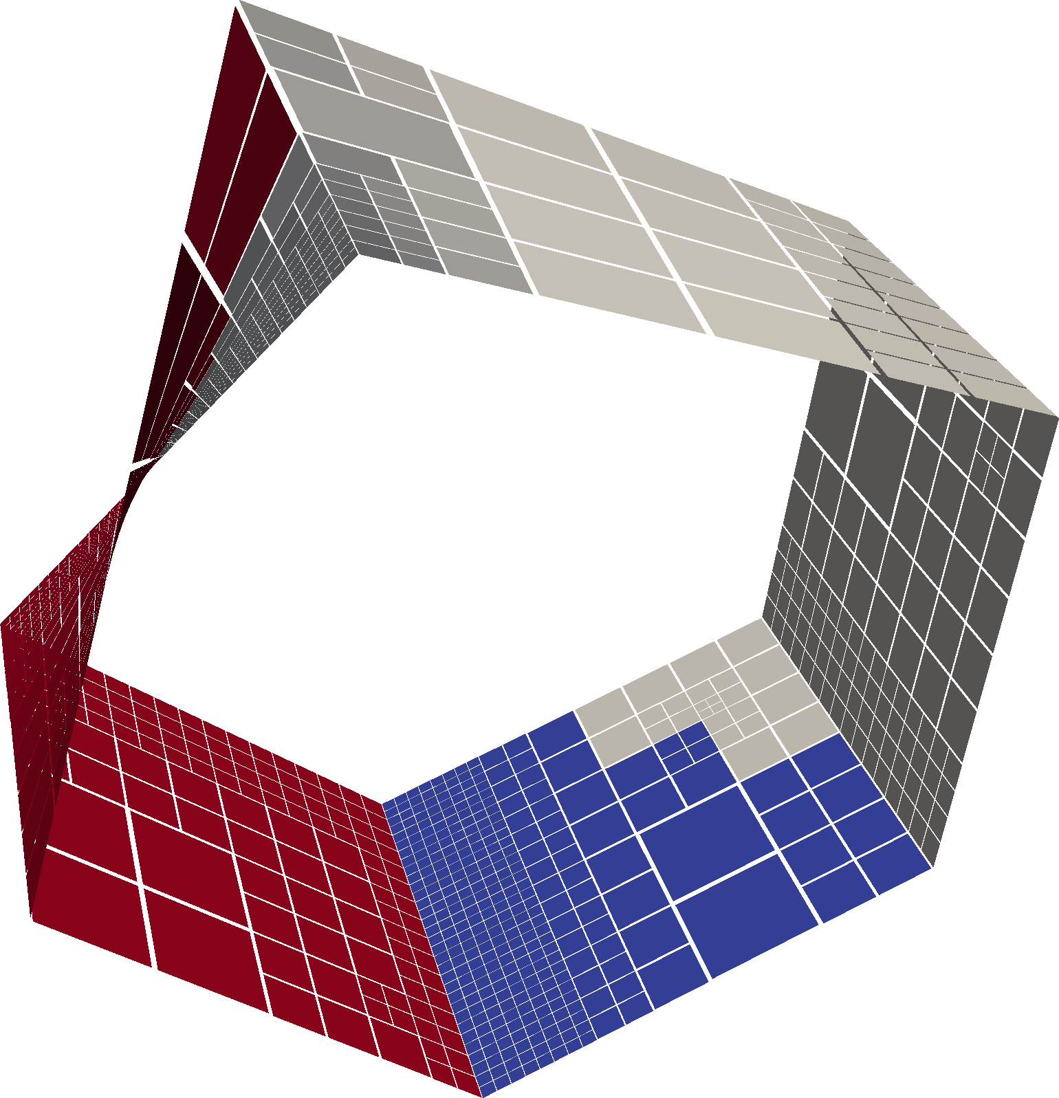
The Moebius strip is an example of a 2D connectivity embedded into 3D space. We construct it from five trees, where an odd number of face connections has a non-standard relative orientation. Note that we do not need to add corner connections to the connectivity data structure for this mesh, since there is no corner connection that is not already a face connection.

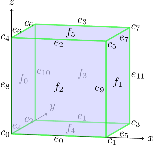
The z-order convention for all boundary entities of a mesh hypercube. This picture shows the 3D case; the 2D case is contained in the x-y-plane. When writing all numbers in binary format, each bit corresponds to a coordinate/normal direction. This convention facilitates dimension-independent programming: All entities relevant to 2D are bitwise reductions of 3D entities.
In principle, there is nothing wrong with allocating and populating the
connectivity yourself.
This is, in fact, a great way to learn the meaning of its members.
However, there are other ways, too.
The easiest is to look through say the
3D connectivity header and call one of our predefined
p8est_connectivity_new_* functions.
We also offer a function to read the connectivity from an Abaqus .inp file.
You may build any numbers of forests with the same connectivity object, but please (a) destroy it only after the last of the forests has been freed and (b) definitely destroy it. It is advised to use the valgrind tool to check for proper deallocation.
Exercise C1:
On one MPI rank, call p4est_connectivity_save,
p4est_connectivity_load and
p4est_connectivity_is_equal to verify that
the connectivity structure survived the file I/O.
Examine its contents with gdb and compare with the documentation
block in the header file.
Further down in the program, collectively call
p4est_connectivity_bcast to replicate the connectivity on all MPI
ranks of the world communicator.
Destroy the connectivities on all ranks.
Use valgrind to make sure no memory is leaked.
Exercise C2:
Write a converter to load your favorite conforming hexahedral mesh format from
disk and populate a p4est connectivity structure in memory.
Use p{4,8}est_connectivity_new to allocate the required memory
once the numbers of trees and edge/corner connections have been determined,
then hand-code a bunch of loops to fill all data fields with values.
Finally, check the object with p{4,8}est_connectivity_is_valid.